
Description
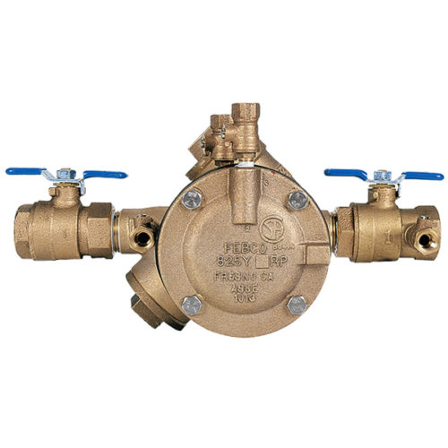
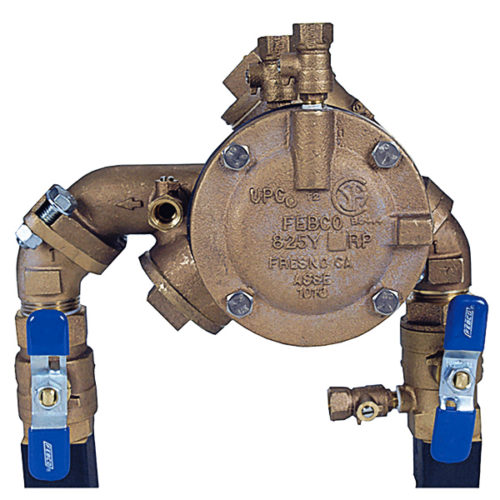
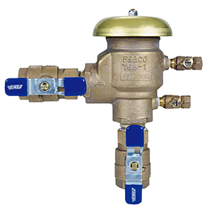
Febco Reduced Pressure Principle Assembly-3/4″
The Febco Reduced Pressure Principle Assembly-3/4″, model 825Y by FEBCO, is used to protect against high hazard (toxic) fluids in water services to industrial plants, hospitals, morgues, mortuaries, and chemical plants. The reduced pressure zone assembly consists of two independently operating, spring loaded, “Y” pattern check valves and one hydraulically dependent differential relief valve. It is used in irrigation systems, boiler feed, water lines and other installations requiring maximum protection. It has an internal relief valve pressure sensing passages, and has simple service procedures. All serviceable parts are in line. The 3/4″ Reduced Pressure Principle Assy has low head loss, and replaceable seat rings on all sizes.
In a flow condition the check valves are open with the pressure between the checks, called the zone, being maintained at least 5.0 psi lower than the inlet pressure and the relief valve is maintained closed. Should abnormal conditions arise under no flow or reversal of flow, the differential relief valve will open and discharge to maintain the zone at least 2psi lower than the supply. When normal flow resumes, the zone’s differential pressure will resume and the relief valve will close.
• Brochure
• Installation
• Maintenance Manual
• Specifications